Main:
Parts/Info
Galleries:
Other:
Older news
| The Miscellaneous page | ||
|
Just a page of some random stuff I have built in the past few... Robots or at least useful electronics, fine line between this stuff and the art page.
|
||
 |
Build Date: Sometime in 1999 My very first Herbie! |
|
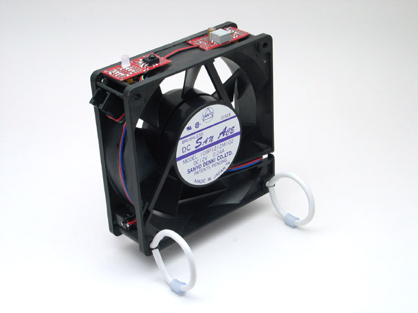 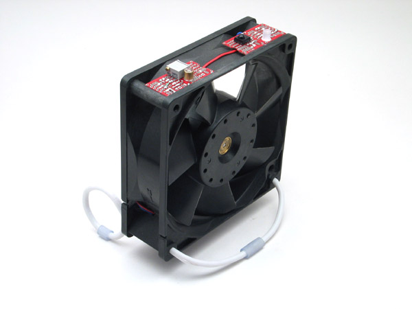 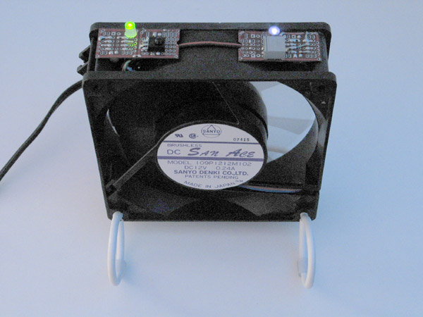 |
Build Date: July 12, 2003 The third variation of Fanbot, this time with a microcontroller! Originally I had planned on doing this with discreet but I need more practice with microcontrollers. Always trying to come up with an easier way to turn these on, you simply wave your hand over this one. To control speed just hold you hand over it and the speed will cycle between fastest and slowest, It also remembers the last speed before it was shut off. The last picture shows the fanbot "on" here you can see the IR LED to the right. The green bicolor LED to the left is used for indicating speeds, power, detection, ect. |
|
 |
Build Date: Apr 24, 2002 Built as a commission gift for LANL, simple edgebot circuit that fits on a single 74AC14 chip. Using these escap motors this draws only 10mA when in operation, so with a fully charged battery it should go for about 6 hours. This detects left and right edge and stops the motor on the side of detection and reverses the opposite side. This is just kind of a neat little bot that will stay on top of a book or tabletop.
|
|
|
|
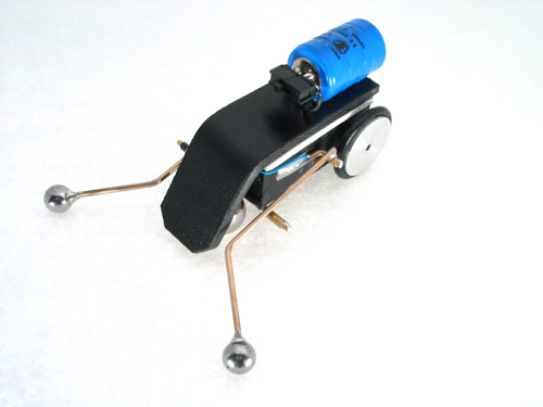
Build Date: Nov 2, 2002 A beetle robot ala Jérôme Demers ( http://members.tripod.com/robomaniac_2001/index.htm) . I just love the simplicity of this device, it uses NO silicon! on top of that it is surprisingly capable. This is built on top of a AAA battery pack. The whiskers are Teflon coated so that they will just slide off of any obstacles. For the front skid I used a polycarbonate ball, it works alright but it is a bit soft for this application. I changed the angle that the sensors were at so that it wouldn't get caught in a corner, so that side pressure will also trigger the sensor not just forward pressure.
|
|
|
|
Build Date: Sept 28, 2002 Those BEP PCB's sure are useful. Here I built a voltage regulator that sits in my car and regulates the voltage to an walkman that I have (from 13.8V to 4.8V). Of the two wires coming out the red one is a regulated 5V and the yellow is an adjustable voltage. Also the small switch toggles a latch that will start flashing the green LED, so this somewhat looks like a fancy security device. On a charged pair of 1F caps it will flash the LED for most of the night.
|
|
|
|
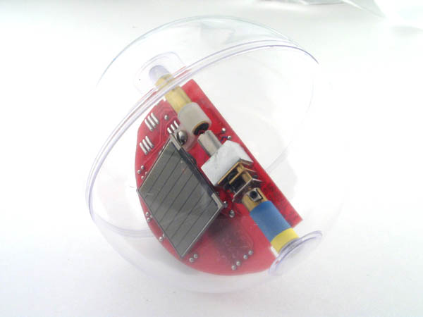
Build Date: Sept 7, 2002 A classic! the Solarbotics miniball, unfortunately this kit is no longer available due to the limited source of the special gear motors used inside. I am still impressed by how little light these will run on due to the solar engine being time dependant and not voltage triggered. *nods to Richard for such a clever idea and Dave for the circuit
|
|
 |
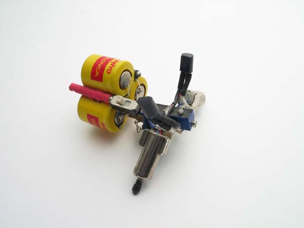
Build Date: July, 2002 Heh, A $5000 Aibo and all I get is the tail... This is the tail module from a first generation AIBO. I much prefer these old AIBO tails to the new ones. Anyway as expected from Sony this tail module was very high quality and fairly easy to hack. I just used a pair of SMD BC2 boards courtesy of Mark T. and attached them to the DC gearmotors inside the tail. For power I used four 1/3 AAA Ni-cad batteries. Also comes complete with a stainless steel belt clip...
|
|

|
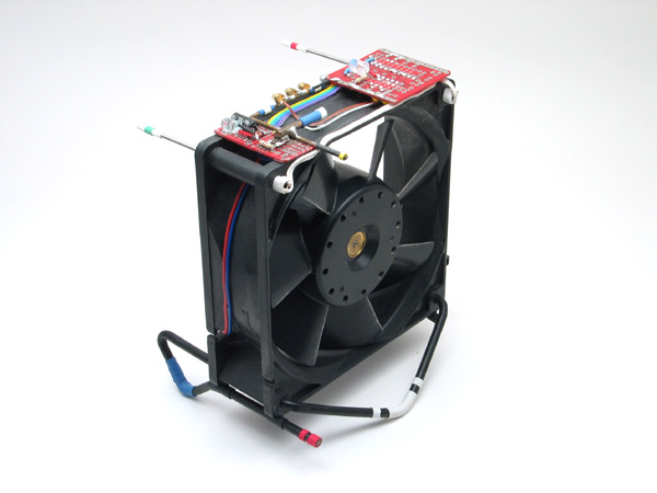
Build Date: July 18, 2002 The second variation of Fanbot Fun and practical, It gets up to nearly 40 deg C in my apartment (104 deg F) during summer, combine that with solder fumes and lack of sleep. Well at least I can stay cooler now. A modified computer fan, and for an added bonus the circuit created has four discreet levels of power, off , low, medium and gale force. These power levels are selected by taping one of the springs sticking out in front. To shut down simply hit that spring again. All the logic for this is on a single 240 chip.
|
|
|
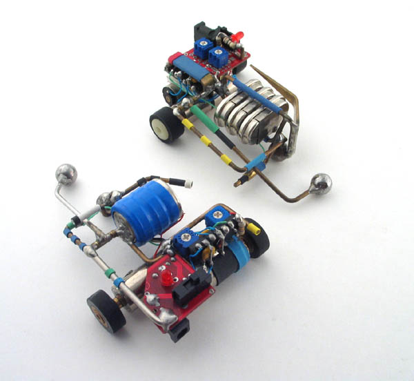
Build date: Jan 27, 2002 and Jan
30, 2002- do you really care which is what?
These are pusher bots that go by the name of Pak and Chooie, I am still working on Umf... do you have stairs in your house? If you didn't get the above paragraph never mind then. These use a 74AC14 for the brain, just a simple reverse turn circuit, probably one of the most basic sumo circuits out there. About 8 months later I figured a way of getting the same behavior out of a pair of relays, a capacitor and an LED while developing circuits for the BEAM book, oh well. And later still I found a way to get improved behavior from a single relay a cap and a resistor, yeesh soon it will be done with nothing and do everything. Isn't that the BEAM dream?
|
|
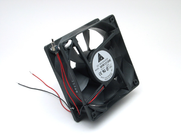 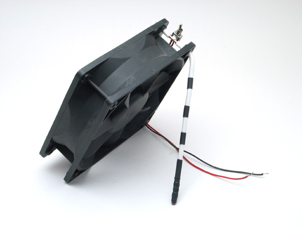 |
Build Date: Aug 12, 2001 The first variation of Fanbot, just a switch and a pair of wires for power. The fan was a bit noisy but quite a bit more powerful than the fans I later used, this one draws 600mA at 12V. The leg can easily be bent to control the angle the fan is at.
|
|
|
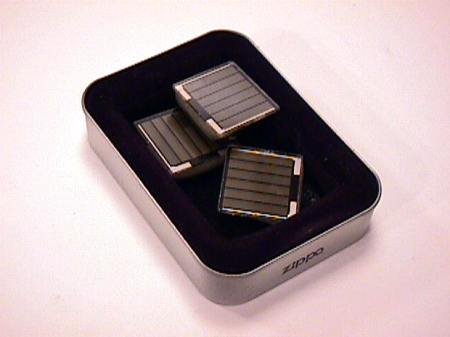
Vibe bots using nice flat
vibrating pager motors.
I left these three in a steel ring overnight with a halogen light overtop of them, when I woke up in the morning they had worn the pattern off of the "fake" wood on my table. Eventually these might wear a hole right through the table, so now I keep them in a zippo lighter container. No light for you! Solar powered polishers? hmmm.
|
|