Main:
Parts/Info
Galleries:
Other:
Older news
|
Circuits
|
|
|
This is a page of circuits that I have used for various robots. All of the circuits here I have personally tested. So unless I made a drafting error these should work if you see any errors or have any questions feel free to E-mail me.
|
|
 |
Created Aug, 2004 A very crude hard drive stepper motor controller. The values here are to run the motor at the maximum speed (I got close to 2400 RPM) that I could get with this circuit. This will require a "kick start" to get it spinning due to the variable range available from the tricore. Basically to get it going you start it at the lowest speed and slowly ramp it up with the potentiometer. I was only able to run this at 5V due to maxing out my lab power supply (3A), the stepper is obviously meant to be chopper driven. It probably wouldn't be that difficult to use the spare three inverters to vary the pulse width sent to the motor, ergo greatly lowering the current consumption. Still I don't think these have the necessary torque to be of much use besides what their intended purpose was but the circuit is out there now. |
|
|
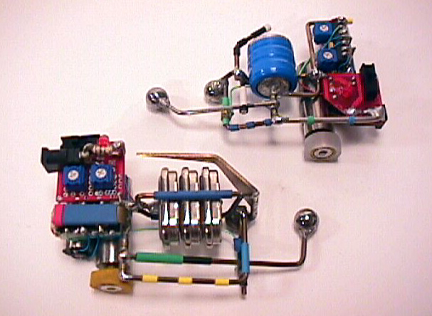
Created Dec 16, 2003 High voltage series LED driver circuit aka, Christmas lights! A rather simple circuit implementing a high frequency oscillator that switches current to a coil once the coil gets shut off the LED's are run off the back EMF. With a pair of series transistors I was getting well over a hundred volt spikes. The transistors are paired due to the 40V breakdown of the Emitter/Collector junction. A simple diode does not work, I suspect that the PN junction capacitance is shunting any back EMF. *MHC stand for Major Henry Coil, check www.solarbotics.com |
|
|
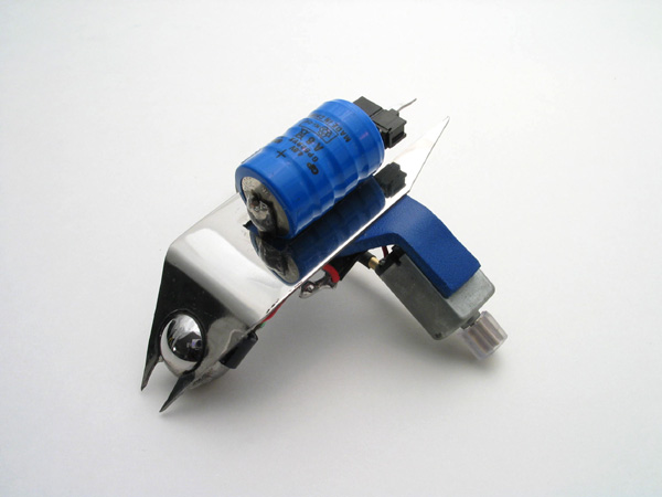
Created: Nov 3, 2003 The Fanbot circuit. The two switches are the springs that stick out front. When both switches are "on" the fan goes gale force. Originally I tried PWM to control the fan speed but found out that the control circuitry inside the fan does not like being shut on and off really fast. So I ended up using the variable conductance of a FET to control RPM of the fan. The 22uF cap is used to get the fan initially spinning, it slows down after a few seconds.
|
 |
Created: June 2003 Single 555 photovore as used on this robot but not including the reverser. Following the same theme as the BBPV type bots, a voltage divider created by a pair of photodiodes is fed into the trigger and threshold. When the voltage divider crosses a 1/3 or 2/3 Vcc value the output will change states. Basically being used as a buffer with hysteresis. Can drive up to 200mA at max voltage of 16V. |
|
|
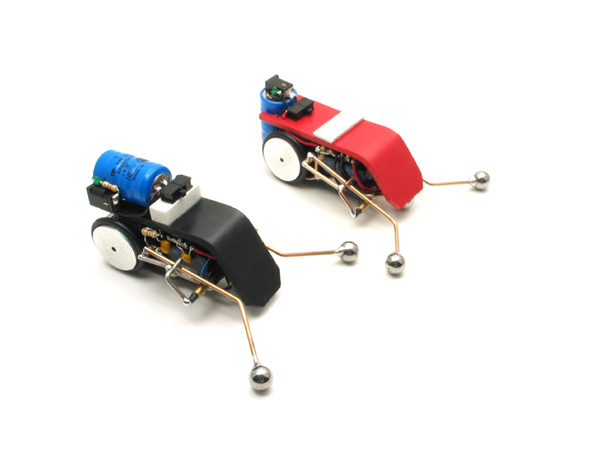
Created: June 2003 Another one chip edgebot, except that this one has two sensors. Depending one which side gets triggered it will back turn left or right. Circuit used on the edgebots here. |
|
|
Created: May 2003 One chip edgebot. This was the original edgebot circuit, built on a single AC14 chip and a few components. The motors are directly driven from the AC14 chip so they should be very low current draw else you will need some sort of motor driver. Behavior is fairly simple, when the switch is triggered both motors will reverse but one will reverse for a shorter time than the other causing it to turn. On the edgebots the timing resistors were replaced with 2 Meg potentiometers. |
|
Created: Feb 2003 Single transistor dark activate circuit. A single transistor circuit does the same thing as the circuit shown below, its a bit simpler but can't run as much current. Suitable for running a few LEDs or another low power circuit. This is actually the circuit I used to create my first solar powered nightlight, to bad a dog eat it, not joking either. The large cap can be replaced with rechargeable batteries for a longer running time. For example if your system voltage is at 2.4V (a pair on Ni-Cads) then the maximum current will be: 2.4V/100K = 24uA So the current is just enough to light up an LED, actually the series LED resistor is not entirely necessary but it is a good design practice to have it there anyway. The gain of the transistor might be much higher than the assumed 100 and burn out the LED.
|
 |
Created: Feb 2003 Two transistor dark activate circuit. A simple two transistor circuit that will run a motor (or any load) when it gets dark. This uses the solar cell at the photodetector. The 100K resistor can be lowered so that it will turn on earlier or raised so it turns on later. The large cap can be replaced with rechargeable batteries for a longer running time. For example if your system voltage is at 2.4V (a pair on Ni-Cads) then the maximum current will be: 2.4V/100K = 24uA These are rough calculations but this should be able to run nearly a quarter of an amp. |
|
|
Created: Feb 2003 Photovore with automatic battery power. A complete photovore circuit with a bit of a twist, it will automatically switch to battery power when it gets dark. Also with a slight change this can be made to charge up a reserve capacitor to quickly get out of dark situations. I used Work time to test this circuit so, kudos to Dave for letting me share it. One important thing to note with this is that battery voltage *must* be lower than the nominal solar cell voltage for this to work. If not it will just run under battery power.
Update: April 15 Added a small feedback capacitor to prevent high frequency oscillations if light level was nearly equal to both photodiodes.
|
|
|
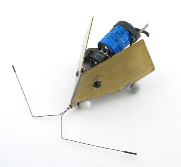
Created: Jan 2003 Solar powered head circuit. The Complete photohead circuit that used the VPM, any regular DC motor should also work. This is the lowest part count head circuit that I can think of... for now. See the robot that uses this circuit here. Also take a look at the movie of this bot in action (1.2MB). |
|
|
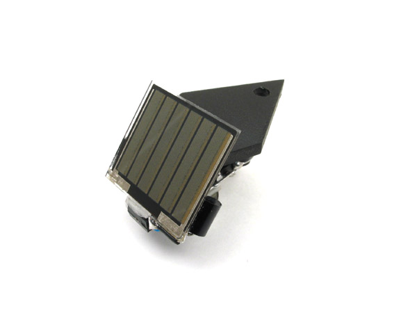
Created: Jan 2003 Simple photovore. This is a *very* simple photovore circuit and can be powered by battery or solar an even simpler version can be built on a 74AC245. The voltage is read from the mid point of a voltage divider crated by two reverse bias photodiodes. As the light changes between the photodiodes the mid point voltage basically slams from + to - with little deadband. Conveniently the AC series has a threshold voltage of very close to half the supply voltage. Also given the tight tolerance on photodiode this usually makes tuning unnecessary. Here is the schematic layout to see how it works easier. |
|
|
Simple photovore with 74AC245. Probably the simplest photovore that I can think of, this is the schematic layout for the robot found here. It works very well, there is only a slight "wag" back and forth probably due to mechanical slop and the lighting conditions. |
|
All Circuits are for personal use only, or at the very least talk to me first. |
|
